Project Background:
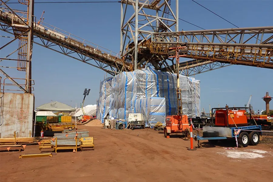
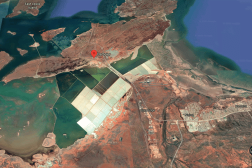
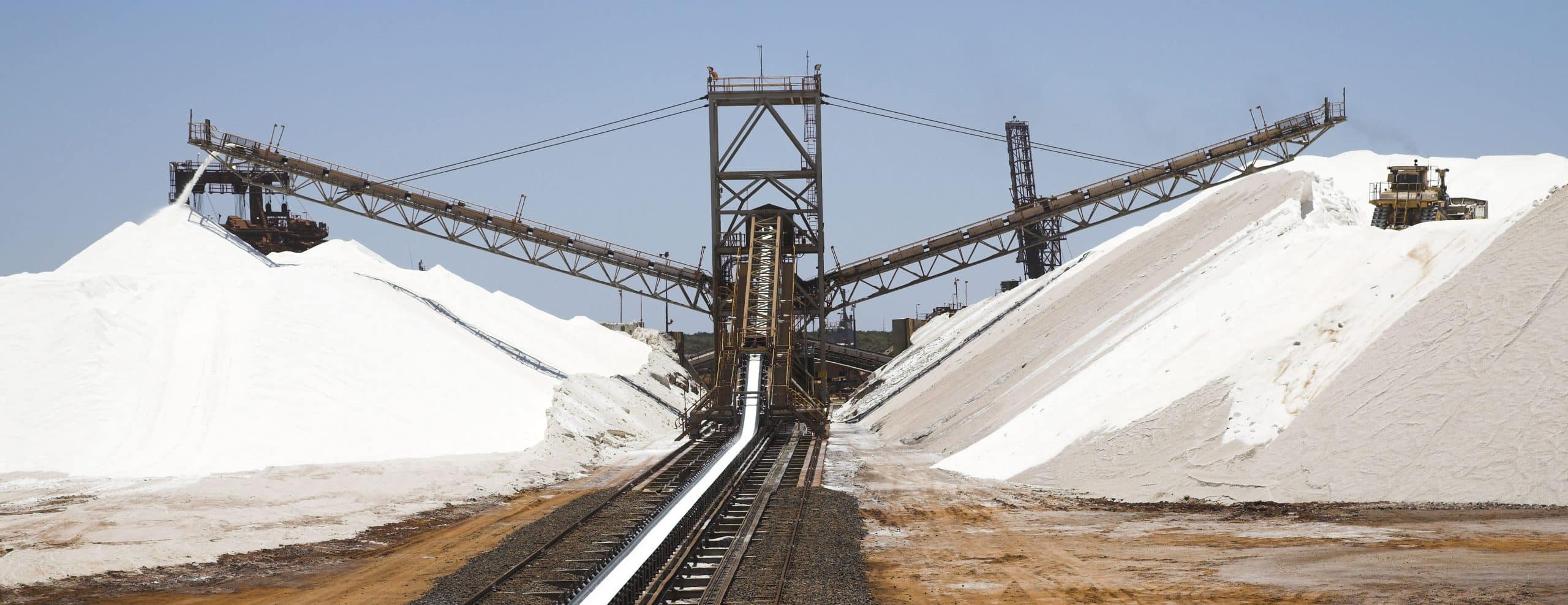
The CV007 fixed stacker was originally installed in 2006 and carried a 1200 mm wide ST 800 belt at 5.6 m/s at a throughput of 3500 tph. The stacker transported dry salt from East Middle Intercourse (EMI) Island to Mistaken Island (MI).
Dozers that operate below the stacker helped to push the salt stockpile into chutes, through which the salt is loaded onto ships. This shows how the stacker played a crucial role in the site.
The design of the stacker featured a cantilevered boom through the main A-frame tower suspended by dual stay ropes above the MI stockpile. But the condition of the stacker had deteriorated to an extent considered beyond economical repair, whereby the primary project owner was seeking to replace the cantilevered section from the pin joint to the head end of the conveyor, inclusive of the front stays.
The assessment of the existing structure and initial options for redesign had already been done by PFS.
Yenem was engaged by BHT to redesign the boom structure.
Scope of Work
Our scope of work comprised of all the work associated with the structural design with the CV007 stacker.
Other key Yenem activities included:
- Two site visits
- Early stakeholder input session
- Construction completion visit
- Basis of Design
- Preliminary design (50% design package)
- Final general arrangement configuration and size of all structural steel members including 3 design options
- Selection of the building material
- Updated Basis of Design based on previous comments
- Confirmed plating/remediation locations with rough sketches of indicative repair details
- General locations of all service routes must be clearly identified
- Detailed design
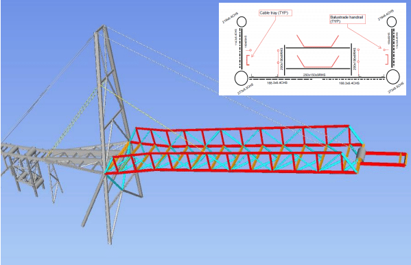
- Design of structural and secondary steel for the replacement boom section (Figure A3). This included the design of all stays and connections; Where practicable, ensure the design is modular and able to be containerized, enabling overseas supply.
- All tie in and modification requirements on adjacent steelwork
- Secondary checks of footing adequacy and design modification if identified following steel design
- (PFS confirmed adequate).
- Identification and specification of all civil/earthworks required prior to, during and following
- Construction, also refer to Sections 2.5 and 3.5.6. This may include:
- Proving bearing capacity of crane pad locations;
- Design of fit for purpose crane pads as deemed appropriate;
- Verification of adequacy of existing geotechnical bearing capacity around footings;
- Sensible sizing and optimisation of material sizes (considering procurement)
- Remove all obstructions north of the head pulley to prevent material build-up.
- Safety in Design and Risk Register
- Constructability review
- Lifting study
- Cable installation
- Temporary supports for dismantlement of existing steelworks
- Structures capacity to support temporary access systems
- Crane pads design at nominated locations during construction
- Constructability review/sequence report
- Answering any technical queries (TQs) that arise from the Company from the commencement of the design until final commissioning.
